Prof Goran Strbac, Prof Paul Mitcheson, Prof Eric Yeatman, Dr Danny Pudjianto and Dr Nunzio Pucci
The team at ICL’s Department of Electrical and Electronic Engineering has analysed the system benefits and impact assessments of integrating space-based solar power (SBSP) into the UK’s future energy mix. The study aims to understand the operational benefits and value of SBSP displacing other low-carbon technologies and carbon infrastructure to meet the UK’s net-zero carbon emissions and energy resilience requirements. The study is conducted on a ‘future energy scenario’ for the 2050 system.
Space-based solar power and its role in the net-zero energy system
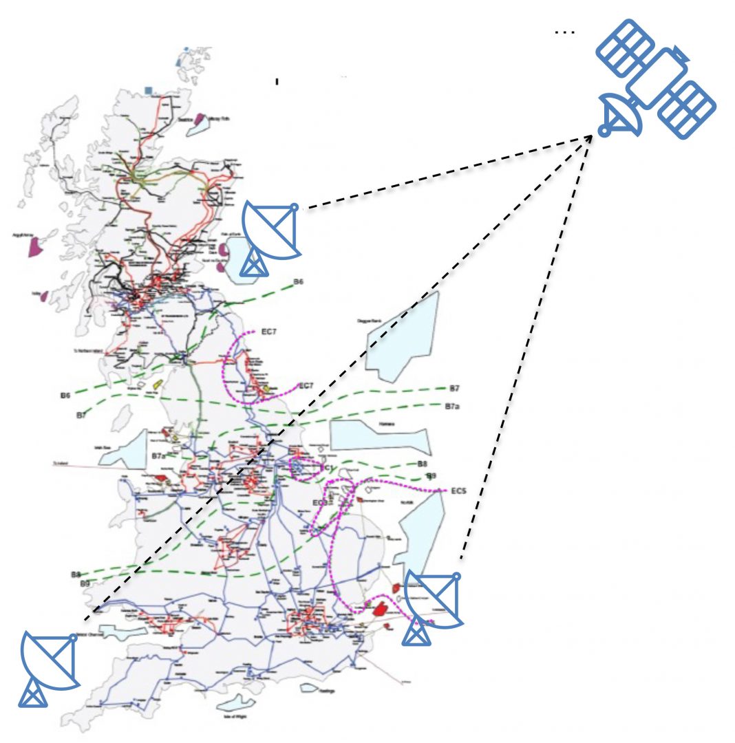
SBSP collects solar power in outer space with solar power satellites (SPS) 24 hours a day, seven days a week and transmits the energy via microwave beams to earth stations. It provides a firm, low-carbon, dispatchable, and directable energy source on the system. The beam can be directed to locations where the value of electricity is the highest without increasing demand for traditional power transmission networks. However, this would lead to time-share utilisation of rectenna connection, e.g. offshore transmission and rectenna collection systems.
System benefits
The initial findings of the analyses suggest:
- SBSP will displace variable renewable sources (vRES) such as wind and terrestrial solar PV, reducing their system integration cost to the system. Increasing the vRES penetration will increase the balancing cost, backup capacity cost, and other supporting infrastructure to transmit and provide flexibility to the system.
- As SBSP provides continuous power, its capacity contributes to generation adequacy, reducing the need for firm capacity such as hydrogen power generation and gas CCS.
- With optimal system planning, SBSP does not compete with nuclear power generation directly, as both technologies are required to support energy resilience and net zero, but this may depend on the cost of those technologies.
- SBSP reduces the generation operating costs driven by low vRES output conditions. The system will rely on gas CCS plants or hydrogen-fired power generation during those conditions to meet the electricity demand.
- Since SBSP reduces the need for wind and terrestrial solar PV, it also reduces the need and cost of flexibility technologies such as electrolysers and hydrogen storage.
- SBSP will reduce transmission network requirements as the energy from SPS can be directed to a different earth station where the value of electricity is the highest.
- SBSP may increase the potential for the largest loss of supply and lead to higher annual costs of frequency services due to its larger capacity (e.g., 2GW) than nuclear plants (e.g., 1.8GW).
- System inertia is significantly reduced in high wind conditions. Since space- based solar power has no inertia, the system and net demand level may be further reduced. During high wind conditions, the required frequency response is increased to deal with the potentially largest infeed loss caused by SBSP.
- Involving low-cost dynamic containment (DC) from electric vehicles (EVs) can significantly reduce the annual system operation cost and the annual cost of frequency services.
- Frazer-Nash Analysis identified 160 viable onshore sites for the rectenna location.
- No redundancy is needed in a rectenna offshore transmission connection, especially if the beam is time-shared between multiple rectennas.
- The rectenna collection system is likely to have a double-sided ring configuration.

System architecture
ICL is also working on a separate project (CASSIE) with Queen’s University Belfast and Satellite Applications Catapult to prove the feasibility of the concept for a scaled indoor demonstrator of the power transmission techniques required to enable space-based solar power.
The basic concept is to use an array of elements (many antennas, separately controlled) in space to generate a focussed beam of electromagnetic energy that travels through space and the Earth’s atmosphere to be received by many receiving antennas in a rectenna ground station.
To facilitate experiments in the anechoic chamber at Queen’s University Belfast, a demonstration of power beaming of 300W over 6.5m will be undertaken, using around 100 transmit and receive elements. Whilst 6.5m is a very short distance for transmission compared to what will be required in a real deployment of space solar power (35,786km), scaling up the number of space-side transmitter array elements and the equivalent receiver array elements allows power to be efficiently transmitted over long distances, and power scales in proportion to the number of elements.
In reality, if the frequency is correctly chosen, there is very little power loss associated with the transmission of power through the atmosphere, and losses are primarily determined by transmitter and receiver antenna and electronics efficiency, assuming that a sufficient number of antenna elements are present on both sides of the link to focus and capture the energy.
While the CASSIE demonstrator is a scale model of the real space solar concept in terms of power and distance, it is being built in such a way that it will enable the performance of a full-scale system to be predicted whilst allowing technical challenges to be identified and addressed.
The direction of the transmitted beam is set by transmitting a pilot beam from the ground receiver station. The space-side transmitters receive this signal and coordinate the phase relationships between all the transmitting antennas to transmit energy back to the ground station through retro-directivity.
The full-scale system requires the following specification:
- The space-side system is expected to be around 2km in diameter.
- Energy density of 200W/m2 received using a receiver array with a diameter of around 5km.
- The system’s operation frequency is selected to be around 2.4GHz, mainly due to the large availability of off-the- shelf components, which can save time and effort, especially during a first-stage assessment of the technology.
- Precise alignment of the transmitted beam with the rectennas can be achieved by employing retro- directivity through a pilot beam.
- Since the geosynchronous orbit is 35,786km, retro-directivity must achieve an error lower than 0.015° to direct the beam in an area of 2 receiver diameters.
- The system is expected to achieve 360° beam steering capabilities.
- The envisioned approach to achieve high-precision steering of the beam is through the design of a specialised phase conjugator circuit, currently in development by Queen’s University Belfast
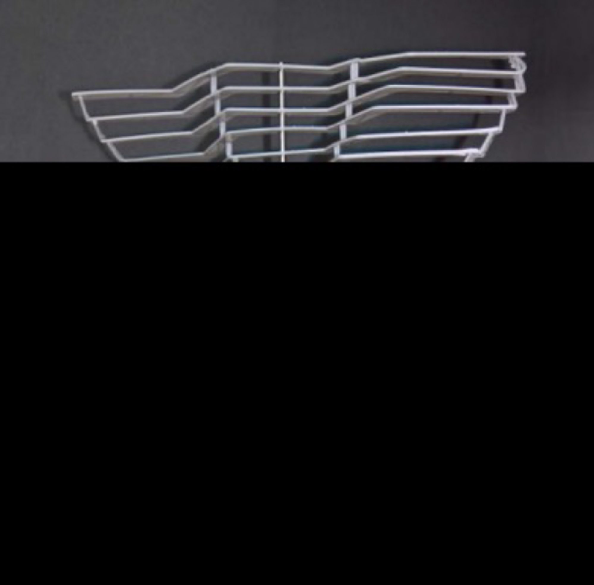
- The original architecture envisioned for the transmitter antenna array is based on the CASSIOPeiA helical array, proposed by Ian Cash (patent application GB2563574)
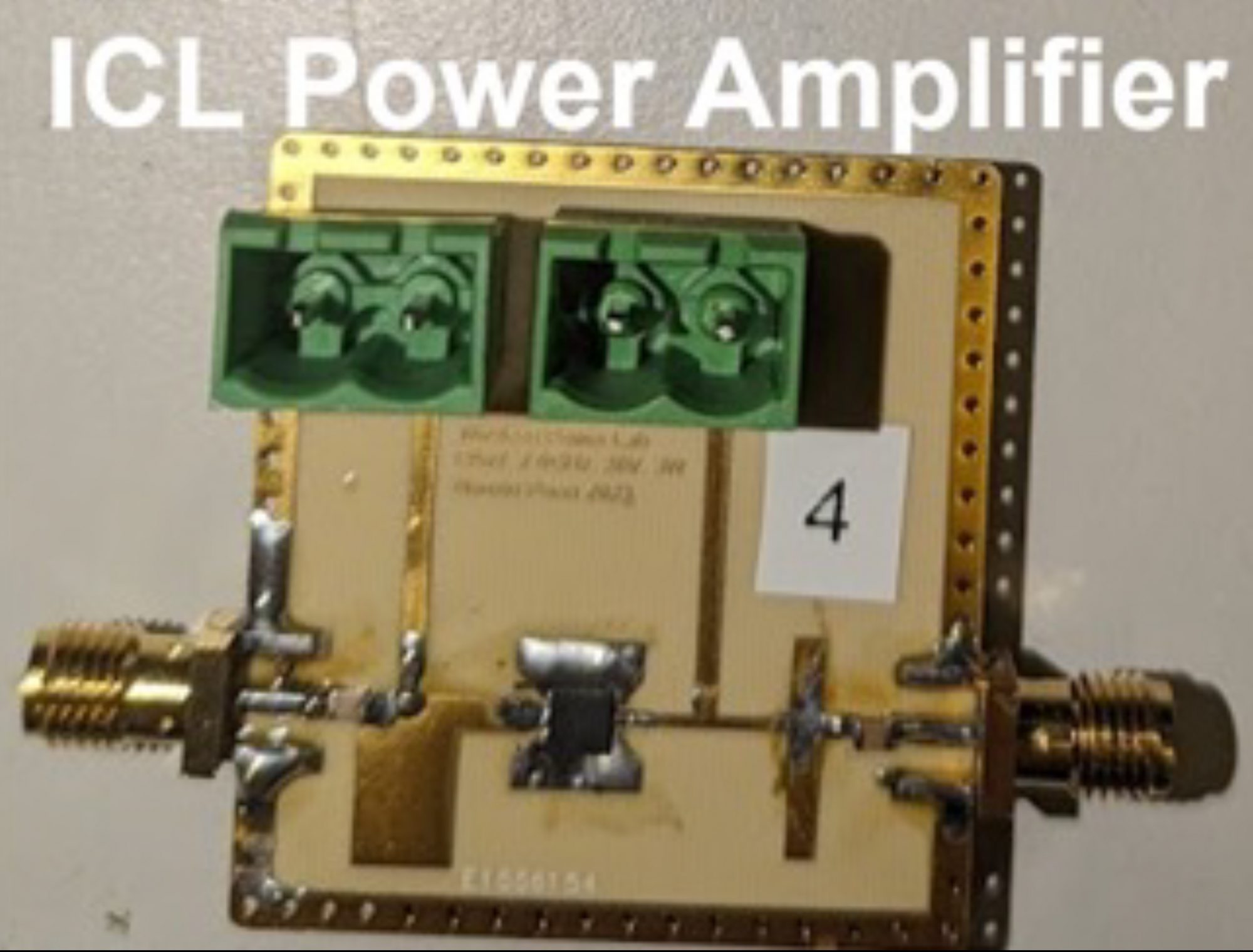
- The current antenna drive circuit architecture on the transmitter side consists of a state-of-the-art Class E Power Amplifier generating 5W with 85% efficiency at 2.4GHz on each antenna element.
- ICL is tackling one of the challenges associated with operating multiple antenna elements nearby: injection of power between transmitting elements. Currently, this problem has been addressed using re-circulators. Still, ICL is working on re-adapting the concept of load independence, previously tested in Megahertz inductive power transfer systems, to Gigahertz power amplifiers.
- Each power amplifier is expected to occupy a maximum area of 6cm2.
- Safety and control of the system, including operability and resilience to hijacking, is currently being investigated by Catapult, which proposed several approaches based on information processing from different ground reference transmitters.

This work is licensed under Creative Commons Attribution-NonCommercial-NoDerivatives 4.0 International.


